*Neurological Imaging *Stereotactic Neurosurgery *Surgical Navigation

header image

Vister3D: Common planning platform for frame-based and frameless stereotaxy


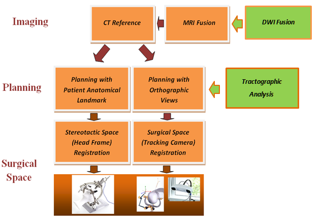
Vister3D is a new prototype of neurosurgical planning platforms for frame-based and frameless stereotactic interventions. Both interventions share the same diagnostic data, - and after archiving, the planning results can be involved in surgical preparation for a different technique. Vister3D offers an ease-of-use planning platform with a generalized solution for conventional arc-based stereotactic head frames:

    Riechert/Mundinger (Inomed Medizintechnik GmbH, Germany);
    MHT (MHT Stereotactic Systems LTD, Germany);
    Leksell (Elekta AB, Sweden),
and frameless navigation interface with Polaris type cameras manufactured by:
Northern Digital Inc., Canada.

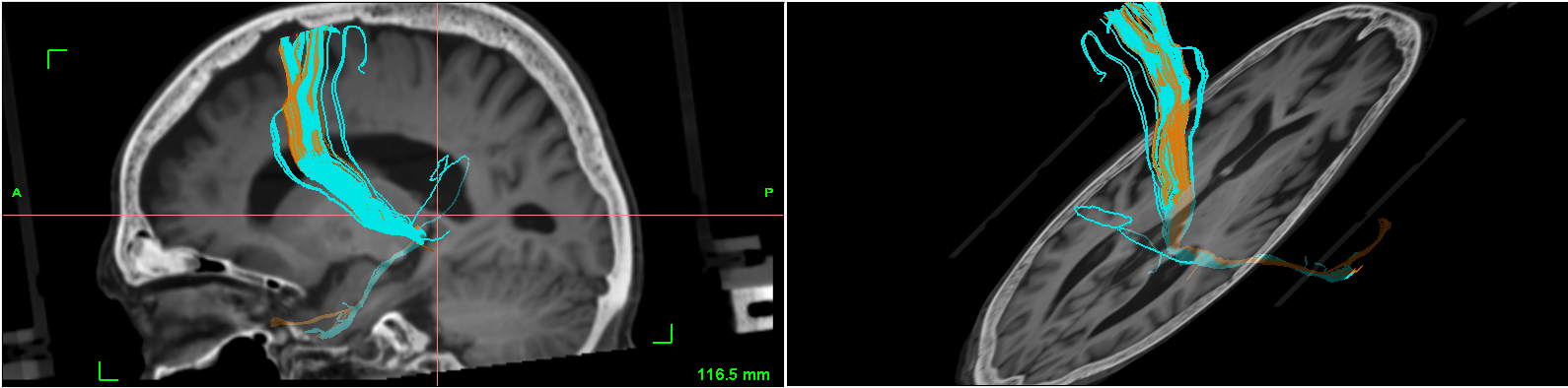
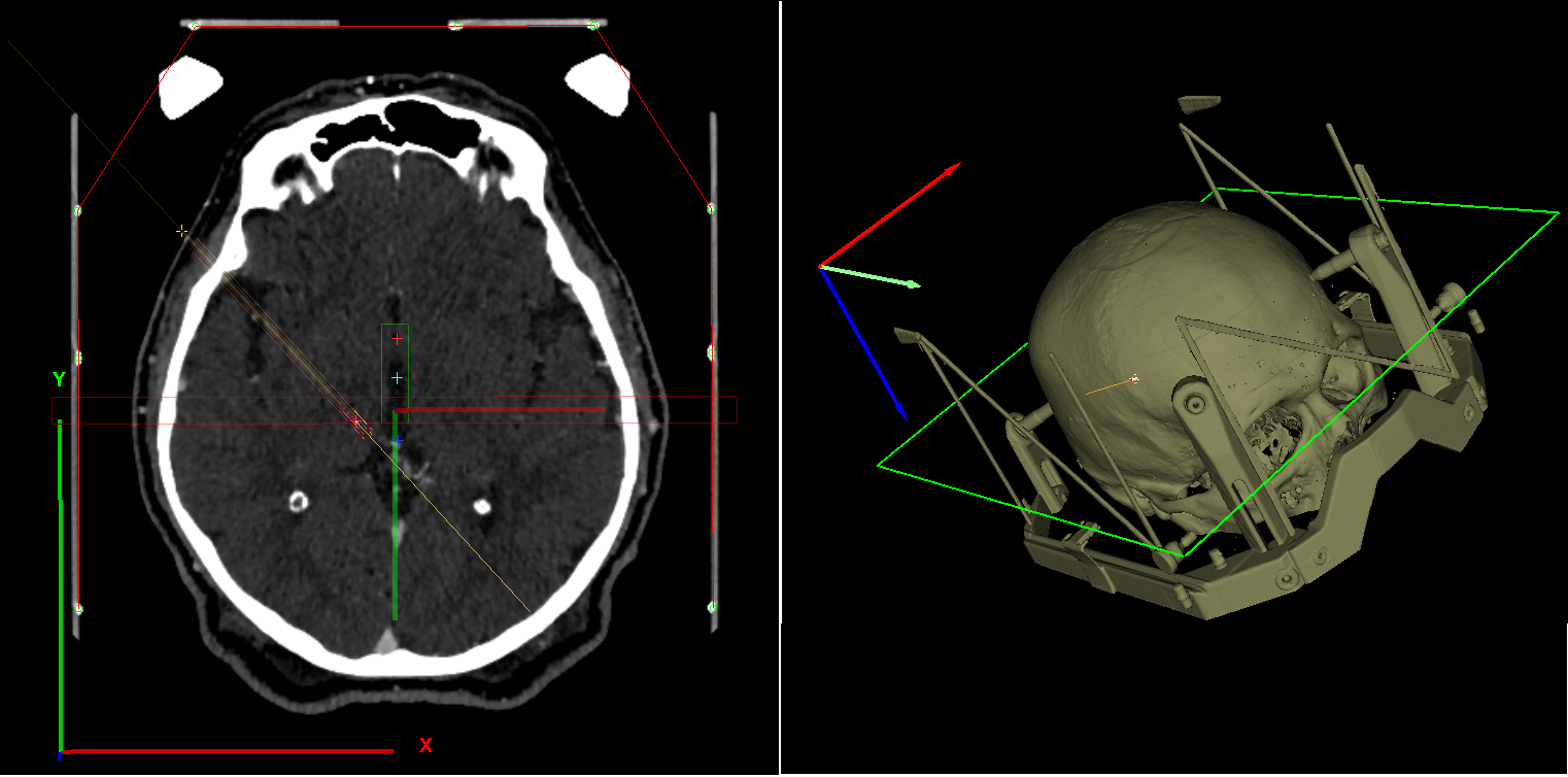
Moreover, the 3D transparency, provided by the software, facilitates accuracy comparisons of frame-based and frameless methods even during the same surgical intervention.


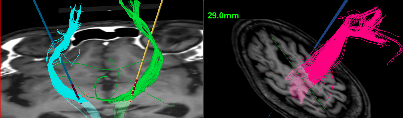
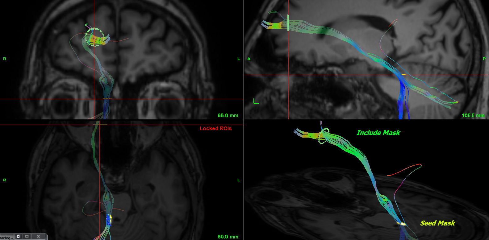
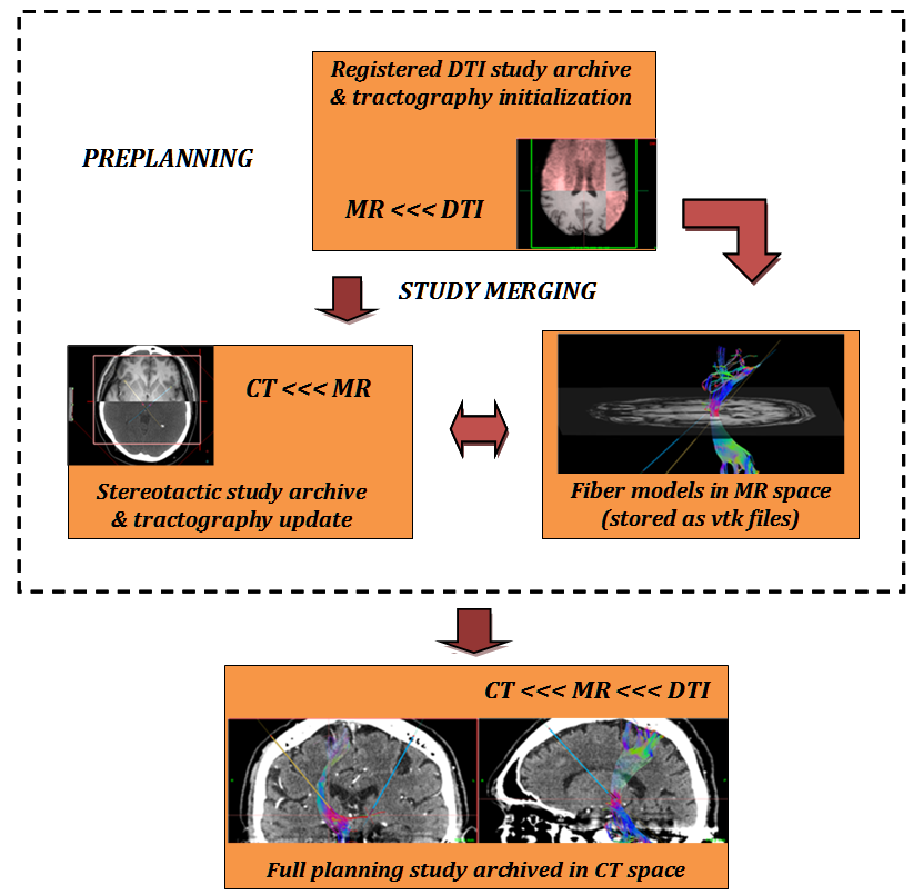
Preplanning is supplemented by DWI (diffusion weighted image) read in and DTI (diffusion tensor imaging) data visualization with GPU-hosted registration to patient MRI. Tractographic analysis can be performed with on-site merging of preregistered archive of fusioned MR and DTI data.

The system has been validated in different brain surgeries: DBS electrode implantology for Parkinson's disease, tumor biopsy or thermolaesio planning for head-arc, frame-based reference and craniotomy planning for frameless navigation to enhance ablating poorly accessible tumors. The modular architecture supports new feature extensions with immediate use in both methodologies. The complex tasks of adding DTI images and running fiber tractography is enhanced by optional backup of studies in compressed archive at different stages of planning. Knowhow for frame-based stereotaxy is co-owned by qualified neurosurgeon (Dr. István Valálik Ph.D. https://parkinson.hu/) who acts as advisor for software development.


Vister3D: Tabulated interface, with modules built up according to clinical workflow

Patient data module for parsing DICOM data and archive studies from easily maintainable database to improve communication regarding diagnostics. Vister3D planning usually relies on three inputs:
    reference CT (always needed);
    fusion MR (to be registered with reference);
    diffusion tensor imaging (DTI) data (optional for tractography, to be registered with fusion MR);
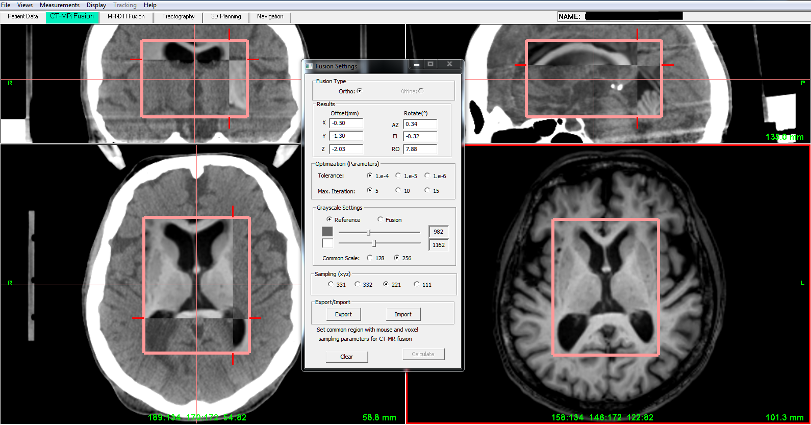
CT-MR fusion module, targeting user selected subvolume with highly optimized fusion algorithm, aligns MR images to CT and visualizes results in orthographic planes;
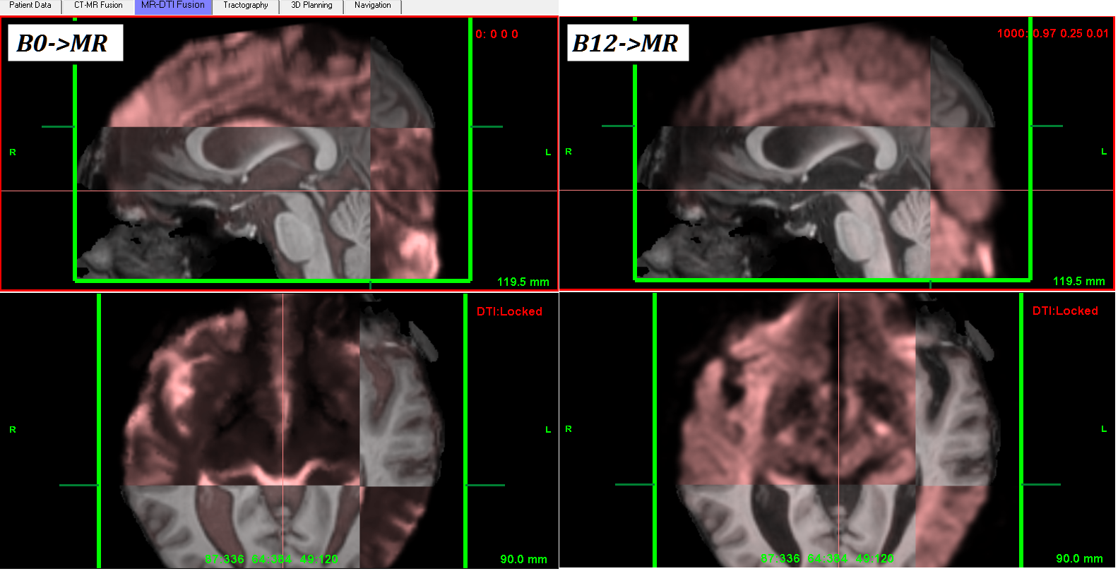
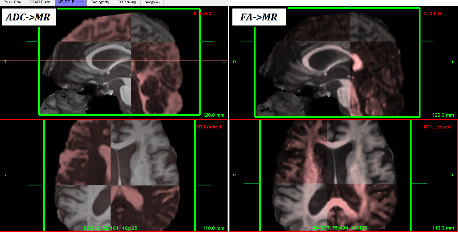
MR-DTI fusion module, register DWI gradient-weighted dataset to MR (using 0 b-value DTI map, as reference) with fast, CUDA-based algorithm. ADC (mean apparent diffusion coefficient) or FA (fractional anisotropy) maps can be fusioned/displayed with MR for diagnostic purposes;
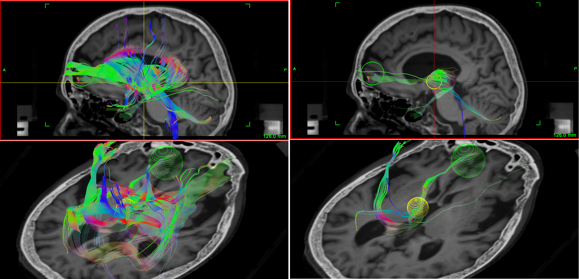
Tractography module, as planning supplement with automatic parsing of registered DTI data and ROIs positioned on anatomical images. Vister3D implements tractography both on original "raw" data and registered DTI data, as well. The unregistered approach relies on "one session" diagnostics with accurate scanner transform both for anatomical and DTI images;
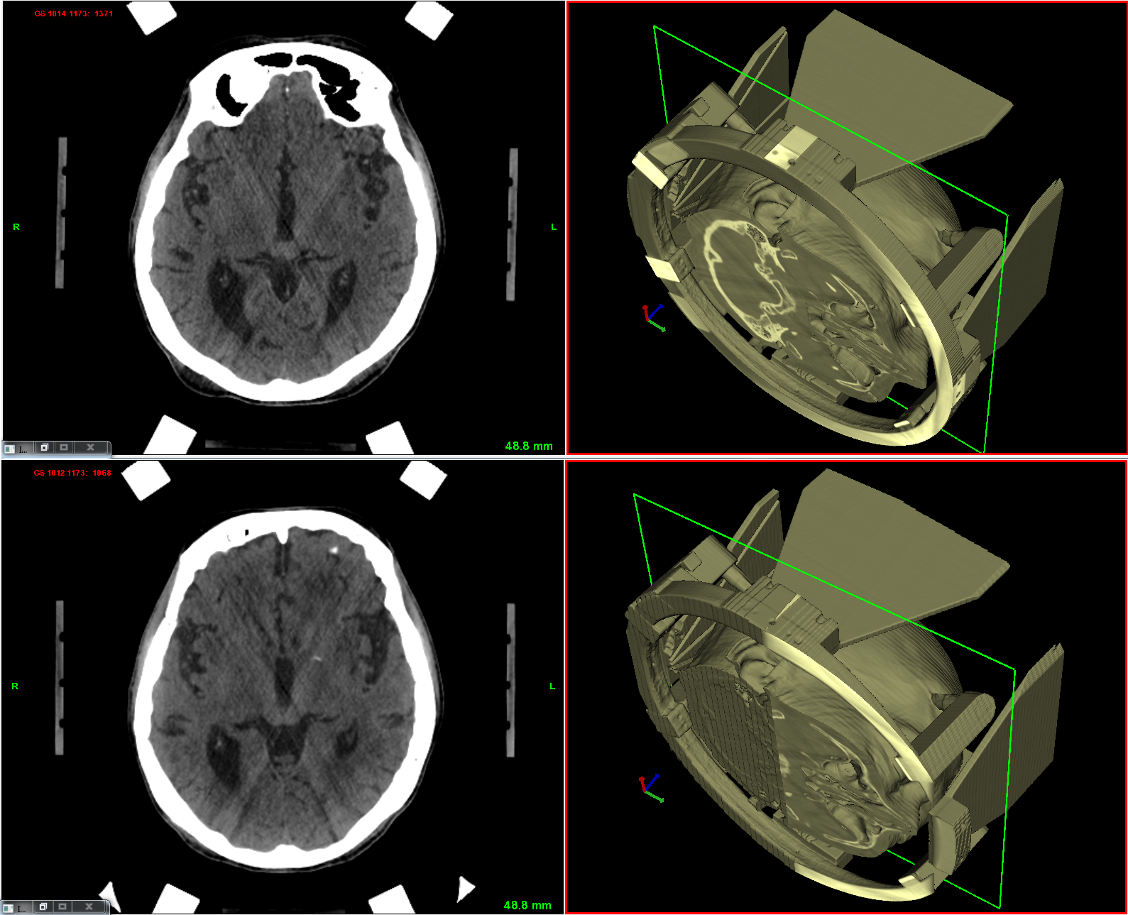
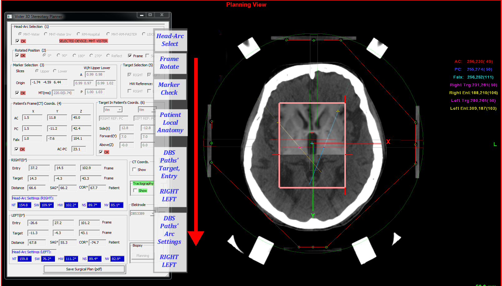
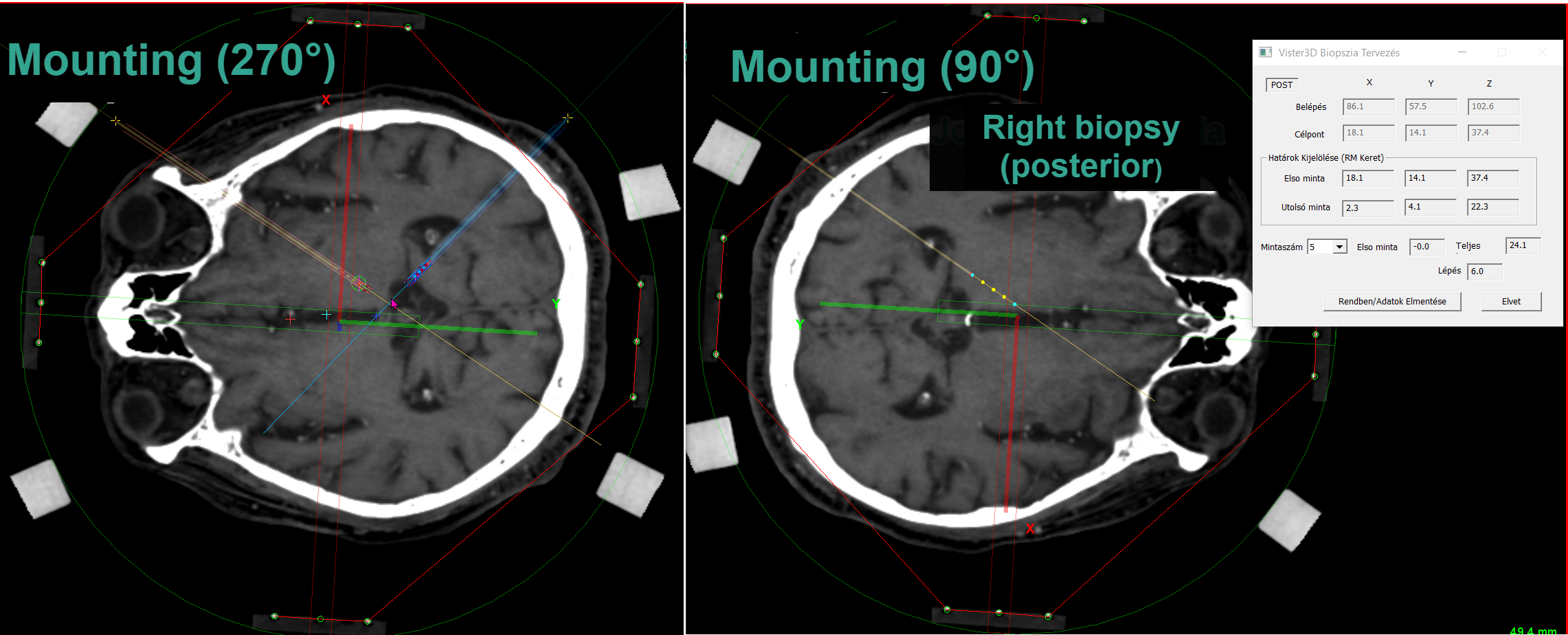
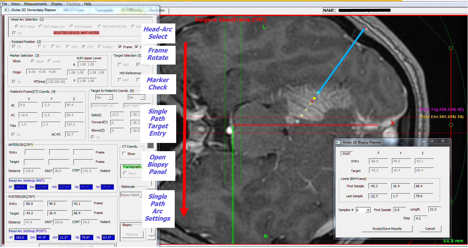
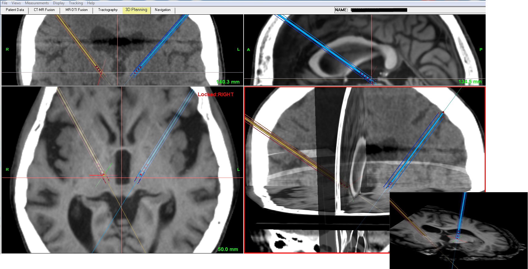
Planning module integrates all operations needed for frame-based or frameless stereotaxy. The calculations are strictly 3D-based that permits an exchange of planning outcome between different platforms. Some of frame-based systems are supported with calculations optimized for anatomical symmetry. Rotated mounting of frame is also possible using common marker set (Vister3D separates marker- and stereotactic spaces for generalized stereotaxy). Real-time feedback is implemented for displaying errors in marker localization and during trajectory planning for coordinates in image volumes and anatomical spaces along with polar settings;
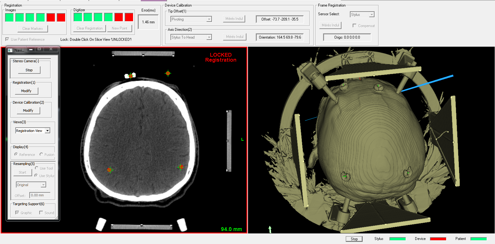
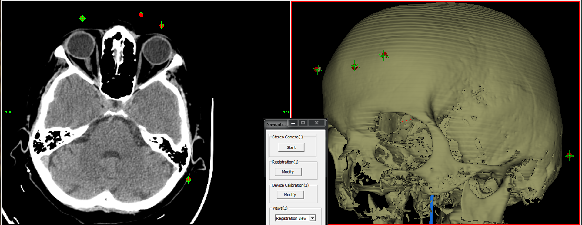
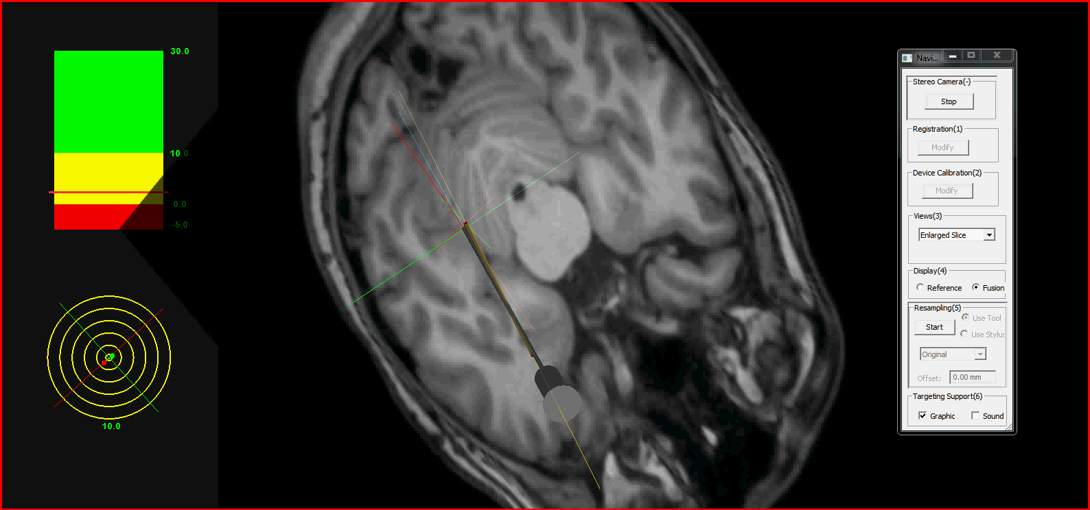
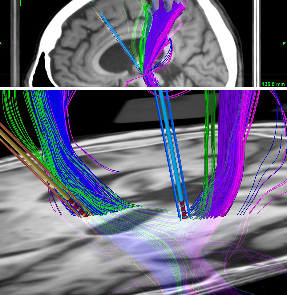
Surgical Navigation module in frameless mode: planning results are usable in optical navigation after surgical space is registered by fiducials. Different tracking modes can be initiated for imaging data using real-time 3D resampling with optional display of fiber models.


Patient data module
dataparsing
Data parsing with display of basic imaging parameters. The root folder contains the patient list with DICOM data (in several formats: .dcm, .nii, .mif etc) and compressed archive files of previous surgical plans (.VTS). The parsing automatically detects DTI data for tractography analysis. Large database can be parsed quickly in a multithreaded solution with options of importing surgical plans or patients' imaging data. Back to modules


CT-MR fusion module
ctmrfusion
CT-MR fusion is based on MI (mutual information) optimization with optional smoothing of CT images. It works with noisy CT reference and T1-T2 MR modalities, and the result is adapted for orthographic planning views. Manual alignment is possible in turn with automatic registration. The fusion is optimized for freely selectable subvolumes but with suitable validation for the whole volume. The enclosed video illustrates the MI optimization if high level of metal artifact is present in CT reference images (fusion_video). Back to modules


MR-DTI fusion module
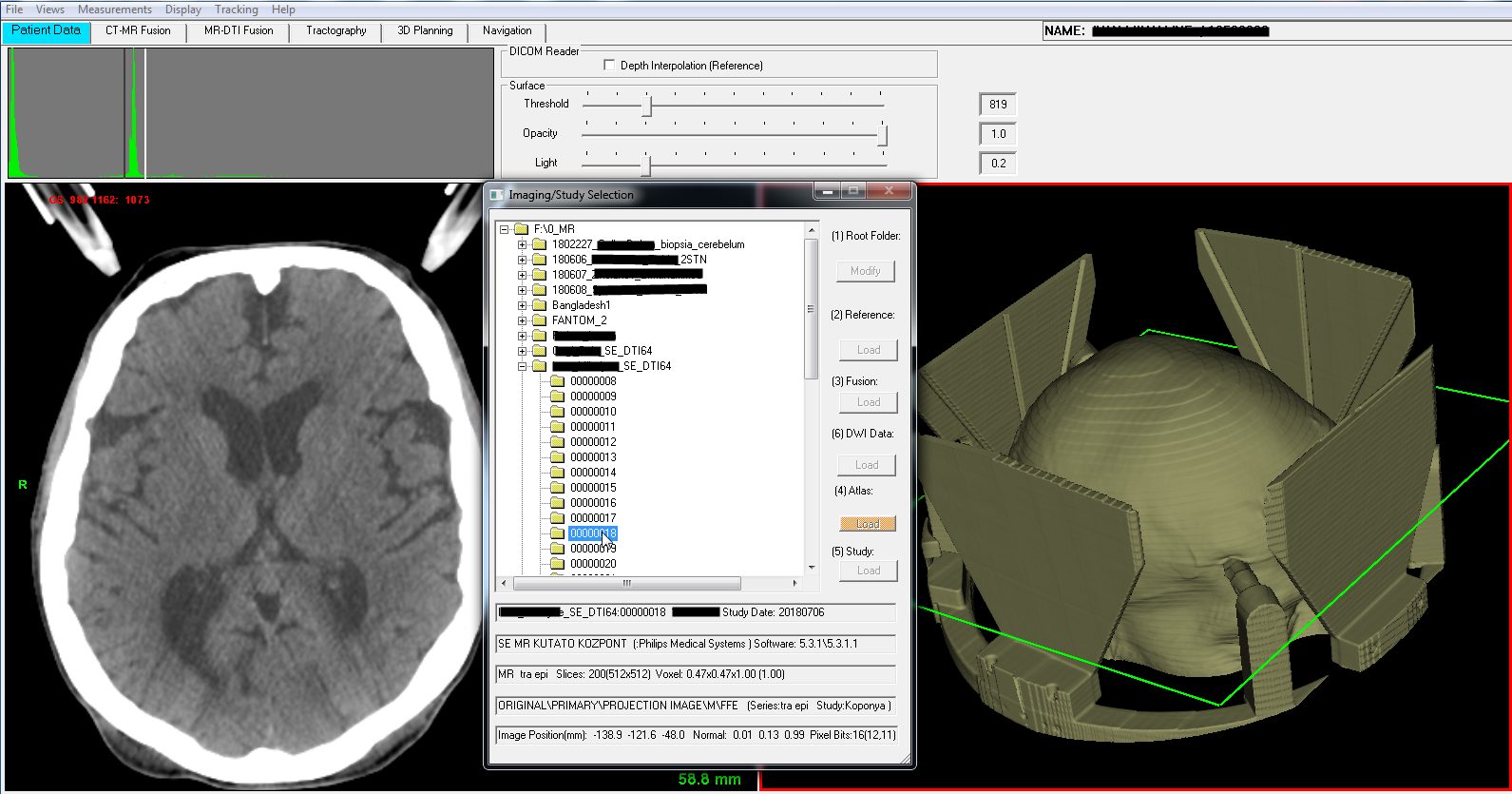
After automatic data parsing of diffusion data found in patient folder, the program generates unregistered DTI mask file and calculates/adds reference DTI volume from tensor images.
Fusion can be executed in next optional ways:
• using patient (or scanner) transforms extracted from DICOM headers (MR and DTI) and neglecting patient’s move during scanning;
• aligning 0 b-value map as reference to anatomical MR and executing motion compensation with CUDA-based algorithm for the full DTI data set;
• adding CUDA-based deformable registration between MR and reference DTI map to find forward and backward displacement fields;
• build up diagnostic imaging with fusioned ADC or FA maps as reference DTI.

mrdwifusion
Comparison of axial and sagital views ofMR-fusioned DTI volumes(left side: 0 b-value map as DTI reference with nonlinear registration to MR, right side: DTI map for a selected gradient registered to MR; in both cases MR mask is activated to improve registration accuracy). CUDA implemented nonlinear image registration of DTI reference consists of two steps: 1/affine step optimizing 12 elements of source-target transform and 2/nonlinear step wich uses geometric moments with diffeomorphic algorithm. Affine step is terminated by preset termination gain. Nonlinear optimization is limited by elastic termination gain, termination cost, max iterations, max time per resolution and max total time. The DTI volumes with nonzero b-value and gradients are registered to deformed DTI reference with affine transforms. This motion compensated data set is archived for tractography. Displacement fields are calculated and stored in stl files for MR to reference DTI and opposite registrations. With these antagonistic sets of displacement fields the seed and target ROI masks for tractography can be deformed into DTI volume and the resulted fiber models can be deformed back from DTI volume leaving the original diffusion data as intact as possible. The calculations are depended on location/orientation of images in scanner space and are adapted to user selected VOIs. This approach with identical VOIs on source and target volumes improves the optimization process and can be the basis for calculating fiber distributions within restricted regions. (DTIfusion_video). Back to modules

fa_adcfusion
Comparison of axial and sagital views ofMR-fusioned ADC and FA maps selected as DTI reference(in both cases MR mask is activated to improve accuracy of deformable registration). ADC and FA maps can be used as reference DTI to register the whole gradient-based dataset. The preferred algorithm is the same as given previously for DTIs referenced by the 0 b-value map. (FAfusion_video). Back to modules


Tractography module
Preferences for using DTI-MR data fusion in fiber modelling during stereotactic planning:
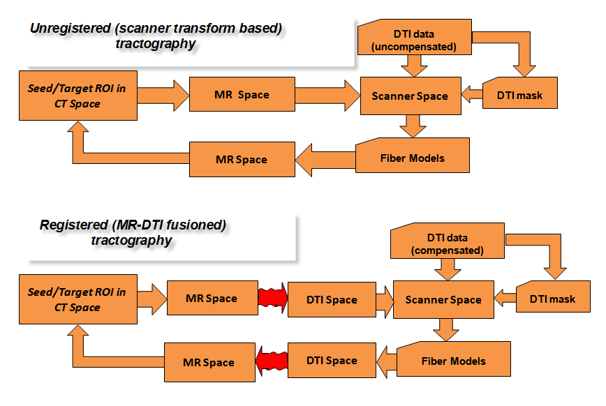
• Unregistered (scanner transform based)approach is very simple, only seed/target ROI mapping needed between the CT reference volume and original, raw MR volume. From there the scanner and DWI spaces can be reached where the uncompensated diffusion data with mask file is used for fiber modelling;
• 0 b-value map as DTI reference,after automatic rotation compensation with scanner transforms, it is aligned to anatomical MR by mouse. Motion compensation is executed with CUDA-based affine algorithm for the full DTI data set with registration to DTI reference. In this case the optimized DTI-MR projection transform is used to reach the diffusion space where the fiber models are calculated with compensated diffusion data and mask file;
• CUDA-based deformable registrationis activated between MR and reference DTI map to find forward and backward displacement fields, followed by motion compensation as before. In this case the MR to DTI nonlinear displacement field is used to optimise seed/target ROI image data during tractography initialization. If tractography finished the resulted fiber models are mapped back from DTI to MR/CT volume using DTI to MR displacement field;
tractography
Tractography analysis in unregistered mode without motion compensation: upper scheme. Tractography analysis in affine/deformable registered mode with motion compensation: lower scheme.Back to modules


Selection of ROIs (spherical or masked types):
tractography
Sphere ROIs:3D-localized seed (yellow), include (green) and exclude types can be used. Seed ROI represents thalamic origin and include sphere is added for filtering nerve bundles. Left views display the distribution based on seed ROI only. These views can be used for initial 3D localization of include ROI. Right views show fibers after repeated calculation with 3D localized include ROI. Back to modules
tractography
Masked ROIs:Contur of seed mask (yellow) and include (green) types are set by mouse in orthographic views. The masked ROI volume is built up by movable/resizeable circle selectable for views (axial, coronar, sagital) with an optional switch to erase mode. This way an accurate 3D ROI mask can be created or edited. The mask depth can be any size from single voxel z step. Fibers tracked from seed ROI mask can be filtered with freely selectable include and exclude subregions. The video displays streamline intercepts along with results of FSL probabilistic tractography generated by FDT ( FMRIB's Diffusion Toolbox) (intercept_video). Back to modules

Comparing unregistered and registered tractography:
tractography
Nerve modelscan be calculated in unregistered mode using scanner transforms (blue) or after deformable registration and motion compensation (orange). Seed ROI represents thalamic origin. Results support the idea to use unregistered mode for fast initial 3D survey of fiber distribution. Back to modules

Tractography initialization for frameless navigation:
ctmrfusion
Frameless navigationcan be supplemented with display of nerve bundles (gradient based coloring): the diagnostic imaging involves fusioned CT-MR data. Real time resampling of imaging is controlled by orientation of stylus with optional offset for cross cursor at stylus tip (value in upper left). The cursor position can be used for 3D measurement between the tip of device and the target area. See sample of stylus controlled navigation (seed ROI located near skull bone) (navigation_video).Back to modules


Planning module

Planning strategies in 3D
Frame-based Interventions: 3D alignment planner to find the best representation of anatomy in imaging;
Stereotaxy planner (Rotated mounting) by computation that helps to find generalized solution for different stereotactic frames. Continuous error feedback is added during marker localization;
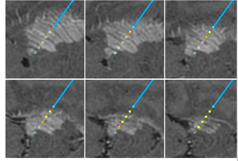
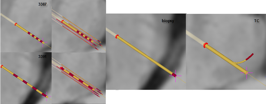
Biopsy planner available in one side planner for biopsy;
Two sides trajectory planner according to anatomical symmetry for DBS (for some frames constrained optimization is selectable to keep left/right mounting on the same arc);
Wide selection of models of DBS electrodes (for stimulation and multiply recordings), biopsy needle and TC (thermolaesio) electrodes;
Export protocols of head-arc settings for operating room and study file storing full dataset of planning.
Frameless Interventions: Orthographic trajectory planner using fusioned and different resampling views with optional data exchange with results of frame-based planning;
Frameless mode:Surgical space registration using fiducials or anatomical markers (comparative accuracy test with frame-based method is possible);
Stylus supported calibration module Navigation of surgical device is possible if its simplified geometry is localized within the space of an attached motion sensor. This can be done with special calibration algorithm, Vister3D is able to simulate several navigated devices or add new surgical tools;
Communication softwarewith Polaris family of motion tracking cameras. Communication with motion tracking cameras from Northern Digital Inc. is configured by separate software which sets USB port connection. Back to modules


3D alignment planner:

ctresampling
Resampling reference imagesaccording to patient specific AC-PC plane. Center of rotation can be relocated and tilt can be defined about all axes. Sequential rotation is implemented according to Euler floating axes scheme. Upper figures display the original CT and reconstructed surface with data coming out directly from scanner. Lower row shows the resampled CT volume according to a user optimized tilt and rotation center relocation. The resampled surface from multiply transformations is displayed in right bottom (with courtesy of Neurosurgery Dept., St. John Hospital, Budapest, Hungary). Back to planning

Stereotaxy planner (Rotated mounting):

rotplanner
Marker spaceis registered to CT reference through intercepts between marker lines and selected image plane. Stereotactic spacecan be identical to marker space or transformed from this base position. Continuous feedback of reconstruction accuracy of marker space ("Marker Check") is possible according to geometrical constraint introduced. The reconstruction of stereotactic space is based on geometry and location of marker plates that offers solution for global accuracy test as a function of marker localization. The planning is divided into several validating steps which are needed to finish step-by-step, in strict order. Clearing any step invalidates all succeeding steps. This figure displays the typical planning view of RM/MHT frames (no rotated mounting added).Back to planning

rotplanner
Stereotactic frame (RM)in surgical view mounted with 270° relative to patient's skull (on left image). During surgery the patient is lying on his right side with plannedleft anterior as well as posteriorelectrode paths. Right image shows the biopsy planning view with RM frame mounted with 90° rotated axes of stereotactic space. The final surgical view displays the real orientation of axes of frame during surgery (patient is lyingon his left sidefor convenient localization ofright posterior entryin DBS). Diagnostic: fusioned CT-MR.Back to planning

rotplanner
Stereotactic frame (Leksell)relocated relative to marker's space (generalized solution for Leksell frame). Vister3D implements stereotactic calculation by distinguishing marker space from stereotactic space that helps integrating majority of head frames currently available. Diagnostic: CT. Back to planning

Biopsy planner:
rotplanner
Biopsy planning in cerebellum with rotated mounting of MHT frame (270° relative to marker's space). After trajectory planning with parameter initialization in the main panel (left side) inset displays the biopsy sampling parameters (right bottom). The sampling locations are selected by simple mouse tracking along the predefined path. Diagnostic background: CT-MR fusioned data with highlighted MR. The figure shows the axes of registered frame as projected into diagnostic view (with courtesy of Neurosurgery Dept., St. John Hospital, Budapest, Hungary). Back to planning

rotplanner
Backup of results of biopsy planning with screenshots taken at each sampling position. Archive file stores frame settings with image screenshots (see example Surgery case in basal ganglia and brainstem...). Back to planning

Selection of models:
electrode_models
Models of Medtronic DBS electrodes (3387-89-91) with recording extensions, biopsy needle and TC (for thermolaesio with pull-out extension) electrode models are available in graphical interface and can be selected for planning. Back to planning


Orthographic trajectory planner:
orthography_mod
Planning for frameless navigationis based on orthographic views with 3D cursor reflecting the actual slice position in each view. Trajectory localization can be started in all views by selecting entry or target points. The planning results are 3D transparent between views used for frame based method and orthographic views for frameless mode. In frameless mode the trajectories can be displayed also in 3 plane mode and surface reconstructed mode. In tracking mode the image at target position can be resampled according to vector identical to path direction (right bottom). Each viewing plane can display reference image and registered fusion image in semi-transparent overlap mode. Back to planning


Tracking/Navigation module

Frameless mode; surgical space registration:
navigation_mod
navigation_mod
Registration panelin frameless navigation module. An optional configuration suitable for comparison with frame-based approach is illustrated in upper view (multi-modality skin markers attached). Lower view illustrates the use of small metal fiducials attached to soft tissue. Surgical space can be registered with 4-6 fiducials and the software provides for full transparency between all integrated 3D spaces (diagnostic volumes, local/global surgical spaces as defined by NDI tracker, patient's anatomical space given by anatomical landmarks, and even stereotactic space of head frame if needed for comparison). The base view of navigation integrates solutions for marker-based registration, device calibration, feedbacks for calculated parameters, errors, sensor visibility tests, etc. Back to planning Back to modules


tracking
Targeting graphics helps navigating device toward target position along a preplanned trajectory. See video for illustration of real time targeting with graphics displaying distance and orientation mismatch between target and navigated device. The accuracy of targeting can be improved by using mechanical guiding support. The presented video represents phantom experiment planned with real data (targeting_brain_video). Back to modules

tumor_tracking
Tumor localizationfor craniotomy in frameless navigation mode. Different resampling views can be synchronized with stylus/tool location and orientation in real time. Reference or fusion images can be selected for viewing. Tumor identification is illustrated by videos with real time resampling according to change of stylus location/orientation (with courtesy of Neurosurgery Dept., St.John Hospital, Budapest, Hungary)(navigation_tumor_videoA; navigation_tumor_videoB). Back to modules


Vister3D: Surgical integration of tractography with preplanning and archiving supports

Vister3D creates very flexible environment for surgical planning: the complex task of DTI registration to anatomic MR can be executed in preplanning step without using CT input. The results of this step are stored incompressed archive fileand can be inserted later into CT referenced stereotactic planning. Compressed archive studies can be generated and merged - with data integrity check - at different levels of calculation (after CT-MR fusion, stereotactic frame registration, trajectory planning, DTI fusion etc). Tractography can be performed not only during preplanning step but during on-site stereotactic planning, as well. The fiber models are exported to vtk file and can be imported later at any phase of planning. This improves the reliability of computations and creates a highly verifiable environment.


Example; preplanning study merged with on-site DBS planning
tractography
DBS planning study with tractography data fusion,video displays fiber distributions near electrodes implanted on both hemisphere (intercepts with seed plane is also shown). Different colors of nerve bundles represent changes in target volume ("include" ROI in cortex)(with courtesy of Neurosurgery Dept., St.John Hospital, Budapest, Hungary).(tract_DBS_video). Back to modules


Vister3D: Company and Support

SurgiFront Ltd. has been owned by Ferenc Pongrácz, Dr. and his son Ádám Pongrácz. After working several years at Yale University (New Haven, USA) on the field of computational neurobiology Ferenc Pongrácz joined in pioneering work for implementing new motion tracking technology into medical applications. He worked for company Artma Biomedical Inc. (located in Salt Lake City, USA) which later moved into Vienna, Austria. He has many years of experience in developing software for various clinical fields listed from human motion analysis, integration of navigated endoscopic view into diagnostics, surgical planning and drill navigation in dentistry and recently stereoactic planning and navigation in neurosurgery. The application has been clinically pretested in routine surgeries with close supervision made by qualified surgeons. Vister3D has been also integrated into treatment of Parkinson's disease at medical care (DBS surgery and other minimally invasive procedures like radiofrequency ablation etc..). The software development has been supported by experts actively participating in open-source fields for medical applications. More info on related works: profile/Ferenc_Pongracz.

Further support can be requested from expert on computational method and surgical use of frame-based stereotaxy (Dr. István Valálik Ph.D. https://parkinson.hu/) and patients' database, workflow management, frameless navigation along with image fusion methods and tractography (Ferenc Pongrácz Dr. info@surgifront.com). Vister3D implements a flexible method for handling hierarchial topology of 3D surgical spaces (get info from Ferenc Pongrácz Dr. info@surgifront.com).

Clinical Sites
Neurosurgical Department of St. John Hospital, Budapest, Hungary (http://www.janoskorhaz.hu/idegsebeszet.html)
Neuromed Private Care, Budapest, Hungary (https://neuromed.hu/)


Contact:

SurgiFRONT Ltd.

Budapest, Zerind Vezér u. 29/B
1029 Hungary
phones: (+36) 305621806, (+36) 12758615
Contact email: info@surgifront.com


Vister3D: Selected Publications

  • M. Truppe, F. Pongracz, O. Ploder, A. Wagner, and R. Ewers, Interventional Video Tomography, in Proceedings of Lasers in Surgery, vol. 2395. San Jose, CA: SPIE, 1995, pp. 150-152.

  • W. Freysinger, M. Truppe, A. R. Gunkel, W. L. Thumfart, F. Pongracz, and J. Maierbaeuerl, Interactive telepresence and augmented reality in ENT surgery : Interventional Video Tomography, Lecture Notes in Computer Science • April 2006, (presented at CVRmed - MRCAS 97, Grenoble, 1997), 1205: 817-820.

  • Pongrácz F., Bárdosi Z. Dentition planning for image-guided implantology. In: Proceedings of CARS (Computer Assisted Radiology and Surgery), Eds: Lemke, HU et al. (Chicago, USA, International Congress Series 1268, 2004 ), pp: :1168-1173

  • Pongrácz F, Renner G. Localized volume matching for the detection of relative displacements in CT or MR images. In: Proceedings of CARS (Computer Assisted Radiology and Surgery), Eds: Lemke, HU et al. (Berlin, Germany, International Congress Series 1281, 2005), p.56-61.

  • Pongrácz F., Bárdosi Z. Proposal for prototyping applications for surgical navigation support. In: Int J CARS (Supplement 1 to CARS 2006, Osaka), Springer, Berlin Heidelberg New York, Eds: Lemke, HU et al. pp:185 -187.

  • Pongrácz, F., Bárdosi, Z. Dentition planning with image-based occlusion analysis. Int J CARS, Springer, Berlin Heidelberg New York, Eds: Lemke, HU et al., 2006, vol: 1 (3), pp:149 -156

  • Pongrácz F., Use of optical motion tracking in application development for surgical planning and navigation, Biomechanica Hungarica, 2008, Ed. Csernátony Z., vol: 1, No.1, pp:21-29.

  • Pongrácz, F. Visualization and Modelling in Dental Implantology (2009). in: “Handbook of Research on Dental Computing and Applications: Advanced Techniques for Clinical Dentistry: Chapter XI”, IGI Publications 2009, Editor: A. DASKALAKI, Max Planck Institute, Berlin, pp:159-169 (see also: irma-international: Chapter 8.9 Visualization and Modelling in Dental Implantology (2009).

  • Pongrácz F., Fusion of video and motion data: engineering tasks and clinical applicability. Biomechanica Hungarica, 2010, Ed. Csernátony Z., vol: 3, No.1, pp: 201-207.

  • Pongrácz F., Video Tracking in Clinical Environment: Framework and Computational Elements. In: : Proceedings of the 1st International CIS Workshop at Budapest, Budapesti Műszaki Egyetem, june 18-23, 2011 (9).

  • Pongrácz F.; Keret nélküli (frameless) stereotaxia és navigációs rendszerek, 5.Fejezet. Valálik I. (Szerk.), Stereotaxiás és funkcionális idegsebészet (Akadémiai Kiadó, Budapest, 2012, 627 old): 75-100. (in hungarian).

  • Pongrácz F., Valálik I.; Common Platform for Evaluating Frame- Based and Frameless Stereotactic Surgery, XXth Congress of the European Society for Stereotactic and Functional Neurosurgery, Cascais/Lisbon, Portugal; 09/2012

  • Pongrácz F., Valálik I.; Common IGS planning, support for frame-based stereotaxy and frameless navigation. 3rd National Conference of Neuro-Oncology, Cluj-Napoca (Kolozsvár), Rumania; 04/2013

  • Pongrácz F.; Visualization and Modelling in Dental Implantology. 33. Hellenic Dental Congress, Athens, 2013, Greece; 11/2013

  • Valálik I., Pongrácz F., Csókay A.; Technique and planning software for stereotactic brainstem and basal ganglia biopsies. XXIst Congress of the European Society for Stereotactic and Functional Neurosurgery, Maastricht, the Netherlands; 09/2014

  • Pongrácz F., Szloboda P., Valálik I.; Fiber tractography and brain atlas integration in stereotactic planning: improving interactivity with multithreaded and CUDA-based solutions. XXII Congress of the European Society for Stereotactic and Functional Neurosurgery, Madrid, Spain; 09/2016

  • Pongrácz F., Szloboda P., Valálik I.; Traktográfiai analízis és atlasz fúzió sztereotaxiás tervezéshez: interaktív módszerek felhasználási lehetőségei. Magyar Idegsebészeti Társaság és a Magyar Neuroonkológiai Társaság Kongresszusa, At Miskolc - Lillafüred, 2016

  • Pongrácz F., Szloboda P., Valálik I.; Tractography in frame-based and frameless stereotaxy: surgical integration with preplanning and archiving supports. XXIII Congress of ESSFN Edinburgh, 26 sept-29 sept, 2018